DEFINITIONS OF SOME QUANTITIES USED IN MEDICAL X-RAY CLINICS
X-ray tube output, Wd,U:
W_{\scriptscriptstyle d,U}= \frac {K_{\scriptscriptstyle d,U}}{I_{\scriptscriptstyle R} \cdot t}where: Kd,U – is the air kerma measured on the central beam axis at distance d from x-ray tube focus for voltage U, IR∙t – is tube-current exposure-time product. In the SI system x-ray tube output is expressed in units of [Gy/C] or [Gy/A·s], usually the tube output is expressed in units of [mGy/mA·s].
Kerma-area product, KAP:
\textit{KAP}=\int_A K_a ~ dAsimplified formula: KAP=Ka*A
where: Ka – is the air kerma measured on area A. In the SI system, the air kerma-area product is usually expressed in units of [Gy·m2]. For x-ray radiation KAP is equivalent of DAP (dose-area product).
Kerma-length product DLP:
\textit{DLP} = \int_L D \left ( z \right )~dzwhere: D(z) – is the absorbed dose distribution alongside the axis of rotation of a CT scanner (z-axis) for a single rotation of a CT scanner (360˚). In the SI system, DLP is expressed in units of [Gy·m].
Computed tomography dose index, CTDI100:
\textit{CTDI}_{\scriptscriptstyle {100}} = \frac 1 {N \cdot s} \int^{+50 mm}_{-50 mm} D \left ( z \right )~dzwhere: D(z) – is the absorbed dose distribution alongside the axis of rotation of a CT scanner (z-axis) for a single rotation of a CT scanner (360˚), s – nominal slice thickness, N – number of slices per single rotation. In the SI system CTDI100 is expressed in units of [Gy].
Weighted CT dose index, CTDIw:
\textcolor{black}{\textit{CTDI}_w = \frac 1 3 \textit{CTDI}_{100,A} + \frac 2 3 \textit{CTDI}_{100,P}} (fantomy PMMA);
where: A – is the axis of rotation of a scanner, P – 10 mm slice thickness from the surface of the phantom. In the SI system, CTDIw is expressed in units of [Gy].
CT pitch factor, CTPF:
\textit{CTPF} = \frac {\varDelta d} {N \cdot s}where: Δd – is the distance moved by the patient coach per a single rotation of the scanner, N, s – see above. CTPF is a dimensionless quantity.
Volume averaged weighted CT dose index, CTDIvol:
\textit{CTDI}_{vol} = \frac {\textit{CTDI}_w} {\textit{CTPF}}In the SI system, CTDIvol is expressed in units of [Gy].
\textit{DLP} = \textit{CTDI}_{vol} \cdot Lwhere: L – total scan length during the examination
Entrance surface dose, Dent:
D_{\scriptscriptstyle ent} = K_{\scriptscriptstyle E} \cdot Bwhere: KE – is air kerma measured at the surface of patient’s skin where the beam enters the patient, B – backscatter radiation from the patient. In the SI system, Dent is expressed in units of [Gy].
Table 1: Rough estimates of backscatter factor for the voltage around 70 kV depending on filtration an beam field size (on the basis of IAEA training materials)
|
HVL | Beam field size (cmxcm)
| ||||
|
mm Al |
10 x 10 |
15 x 15 |
20 x 20 |
25 x 25 |
30 x30 |
|
2,0 |
1,26 |
1,28 |
1,29 |
1,30 |
1,30 |
|
2,5 |
1,28 |
1,31 |
1,32 |
1,33 |
1,34 |
|
3,0 |
1,30 |
1,33 |
1,35 |
1,36 |
1,37 |
|
4,0 |
1,32 |
1,37 |
1,39 |
1,40 |
1,41 |
Entrance skin dose, ESD:
\textit{ESD} = K_{\scriptscriptstyle E} \cdot B \left ( \frac \mu \rho \right )^{skin}_{air}
where KE – is air kerma measured at the beam axis on the patient’s skin, B – backscatter factor from the patient, (μ/ρ) – mass absorption coefficient skin-to-air. In the SI system, ESD is measured in units of [Gy].
Table 2: Mass absorption coefficient for skin, air and skin-to-air for selected voltages (on the basis of ICRU-44 and J.H Hubbell and S. M. Seltzer)
|
Energia [keV] | | | |
|
50 |
0,2264 |
0,2080 |
1,0885 |
|
60 |
0,2048 |
0,1875 |
1,0923 |
|
80 |
0,1823 |
0,1662 |
1,0969 |
|
100 |
0,1693 |
0,1541 |
1,0986 |
|
150 |
0,1492 |
0,1356 |
1,1003 |
RELATIONSHIPS BETWEEN SOME QUANTITIES USED IN X-RAY CLINICS
Relationship between kerma (dose) and distance:
K_{\scriptscriptstyle 1} = K_{\scriptscriptstyle 2} \left ( \frac {r_{\scriptscriptstyle 2}} {r_{\scriptscriptstyle 1}} \right )^2where: ri – is the distance from the tube focus, Ki – is the air kerma (dose) at distance ri
Relationship between kerma and kerma-area product (KAP):
K_{\scriptscriptstyle S} = \frac {\textit{KAP}} {A_{\scriptscriptstyle S}}where: KAP – is the measured kerma-area product, AS – radiation field in the plane perpendicular to the beam axis at point S, KS – kerma at point S. For x-ray radiation KAP is equivalent to DAP.
Relationship between beam field sizes:
A_{\scriptscriptstyle 1} = A_{\scriptscriptstyle 2} \left ( \frac {r_{\scriptscriptstyle 1}} {r_{\scriptscriptstyle 2}} \right )^2where: ri – is the distance from the tube focus, Ai – beam field size at distance ri
Calculating kerma at point E based on measured tube output:
K_{\scriptscriptstyle E} = W_{\scriptscriptstyle d,U} \cdot I_{\scriptscriptstyle R} \cdot t \cdot \left ( \frac {r_{\scriptscriptstyle d}} {r_{\scriptscriptstyle E}} \right )^2where: Wd,U – is the tube output calculated in point d for voltage U, IR·t – is the tube-current exposure-time product, rd – distance between the point where output was measured, Wd,U, and the tube focus, rE – distance of the point where kerma KE was determined from the tube focus.
GENERAL ALGORITHM FOR CALCULATING ENTRANCE SURFACE DOSE AND ENTRANCE SKIN DOSE
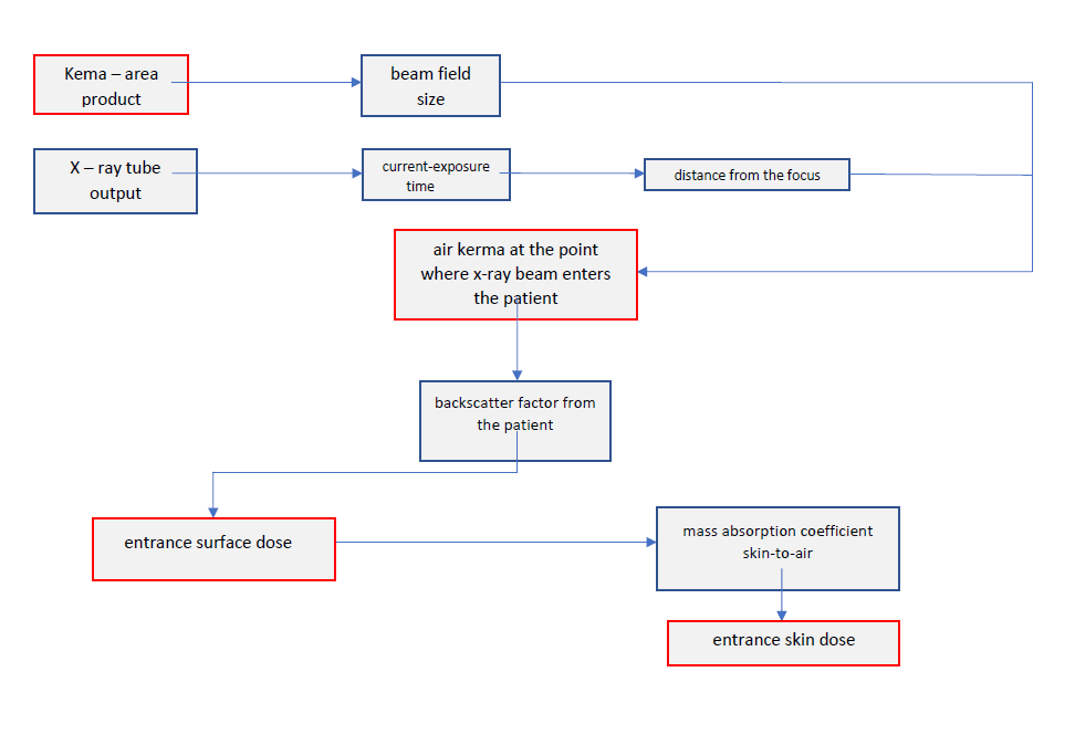
Simplified calculations:
For more information see:
- H. Aichinger, J. Dierker, S Joite-Barfuss, M.Saebel: Radiation Exposure and Image Quality in X-ray Diagnostic Radiology (Springer 2004, ISBN 3-540-44287-1) link
- Entrance skin dose estimates derived from dose-area product measurements in interventional radiological procedures, B. J. McParland, BJR, 71 (1998), 1288 – 1295 link
- A study of patient radiation doses in interventional radiological procedures B.J. McParland, BJR, 74 (2001), 727 – 734 link
- Differences in effective dose estimation from dose-area product and entrance surface dose measurements in intravenous urography E. Yakoumakis at al, BJR,, 74 (2001), 920 – 925 link